Architecture drawing
Architecture drawings are essential visual representations that convey design intent, technical details, and the overall concept of a project. These drawings are used by Architects, engineers, contractors, and clients throughout the design and construction process. Below are the main types of architecture drawings and their purposes.
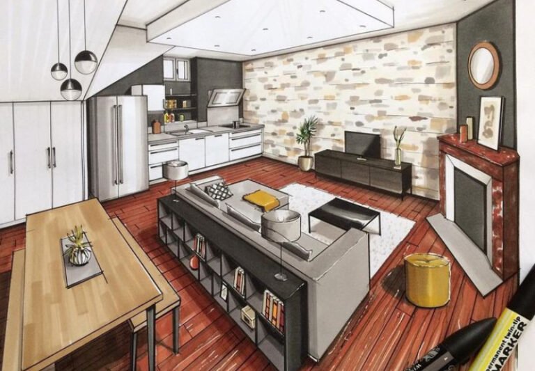
1. Conceptual Drawings
Purpose: Illustrate the initial ideas and overall vision.
Examples: Sketches, bubble diagrams, and conceptual layouts.
Tools: Hand-drawn sketches or software like sketchup
Conceptual drawings are preliminary visual representations of design ideas, showcasing layouts, styles, and concepts. They help convey the overall vision for a space, allowing clients and designers to discuss and refine the design direction before detailed plans are developed. These drawings are key in visualizing the project’s potential.
2. Site Plans
Purpose: Show the relationship between the building and its surrounding environment.
Details Included: Landscaping, pathways, roads, utilities, and neighboring buildings.
Site plans are detailed drawings illustrating the layout of buildings and their surroundings. They show boundaries, structures, landscaping, and utilities, helping ensure designs are practical, comply with regulations, and fit seamlessly within the environment for efficient space utilization.

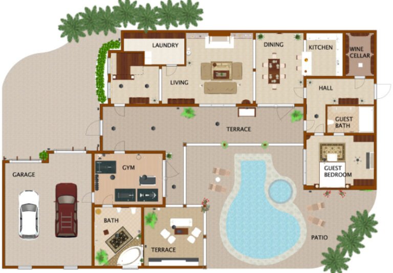
3. Floor Plans
Purpose: Provide a top-down view of the building’s layout.
Details Included: Walls, doors, windows, furniture, and room labels.
Common Scale: 1:100 or 1:50
Floor plans are scaled drawings that represent the layout of a building’s interior, showing walls, doors, windows, and rooms. They provide a clear view of space organization, helping designers, architects, and clients understand how a space functions and flows, ensuring an efficient and functional design.
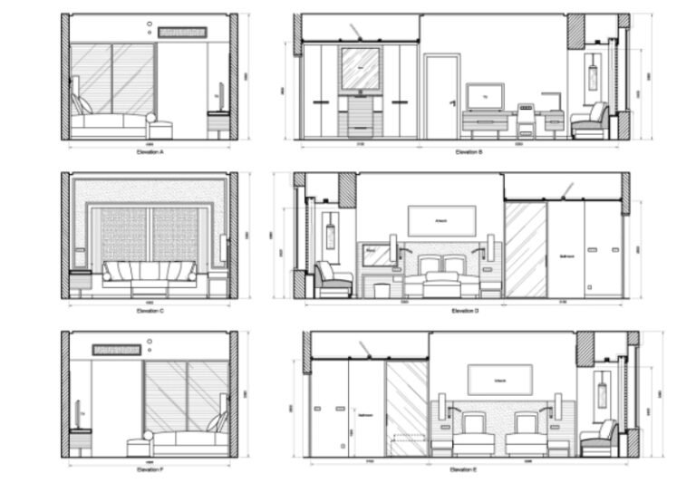
4. Elevation Drawings
Purpose: Show the exterior view of each side of the building.
Details Included: Facades, materials, heights, and architectural elements.
Elevation drawings are detailed illustrations of a building’s exterior from a specific viewpoint, showcasing its façade, height, and design elements. These drawings highlight architectural features like windows, doors, materials, and textures, helping to visualize the building’s appearance and ensuring the design aligns with aesthetic and functional goals.
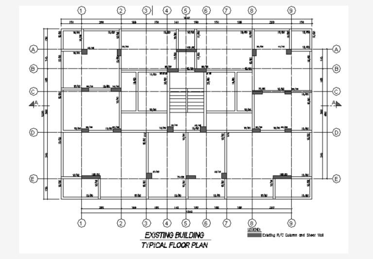
5. Structural Drawings
Purpose: Outline the structural framework of the building.
Details Included: Beams, columns, foundations, and load-bearing elements.
Structural drawings are detailed plans that outline the framework and support systems of a building. They include information about foundations, beams, columns, and load-bearing walls. These drawings ensure the building’s stability and safety, providing essential guidance for construction teams to execute the design accurately and securely.
6. Mechanical, Electrical, and Plumbing (MEP) Drawings
Purpose: Illustrate the building’s utility systems.
Details Included: HVAC layouts, electrical circuits, and plumbing schematics.
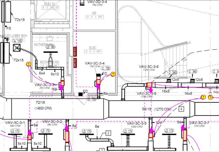
MEP drawings detail the mechanical, electrical, and plumbing systems of a building. They illustrate the placement of HVAC units, electrical wiring, lighting, and plumbing pipes. These drawings ensure that all systems are properly integrated, functional, and comply with safety standards, supporting efficient building performance and occupant comfort.

7. 3D Renderings and Perspectives
Purpose: Provide a realistic visualization of the design.
Tools: Software like AutoCAD, Revit, or Blender.
3D renderings and perspectives are realistic visual representations of a design, created using computer software. They provide a lifelike view of a space or structure from various angles, helping clients and designers better understand the aesthetic, spatial relationships, and overall feel of a project before construction begins.
8. As-Built Drawings
Purpose: Document the final construction for maintenance or future renovations.
Details Included: All modifications made during construction.
As-built drawings are accurate representations of a building or structure as it was actually constructed, reflecting any changes made during the construction process. These drawings show the final dimensions, materials, and layout, serving as a reference for future renovations, repairs, or maintenance, ensuring precise documentation of the completed project.



